Both p-type and n-type silicon will conduct electricity just like any conductor; however, if a piece of silicon is doped p-type in one section and n-type in an adjacent section, current will flow in only one direction across the junction between the two regions. This device is called a diode and is one of the most basic semiconductor devices.
A diode is called forward biased if it has a positive voltage across it from from the p- to n-type material. In this condition, the diode acts rather like a good conductor, and current can flow, as in Fig. 4.13.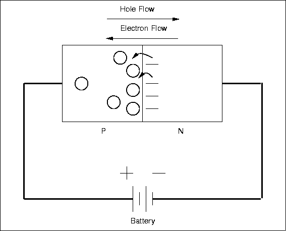
There will be a small voltage across the diode, about 0.6 volts for Si, and this voltage will be largely independent of the current, very different from a resistor.
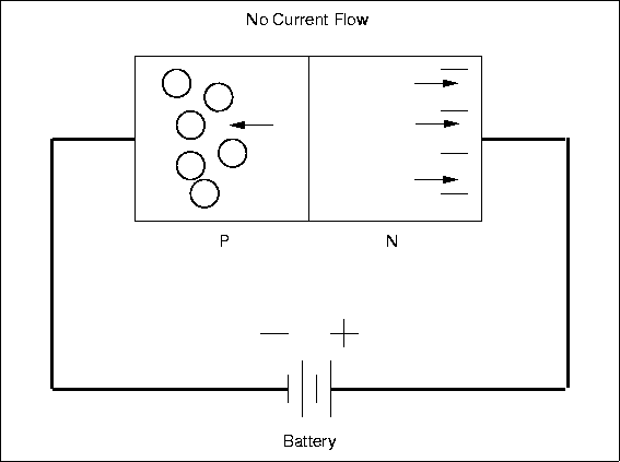
If the polarity of the applied voltage is reversed, then the diode will be reverse biased and will appear nonconducting (Fig. 4.14). Almost no current will flow and there will be a large voltage across the device.
The non-symmetric behavior is due to the detailed properties of the pn-junction. The diode acts like a one-way valve for current and this is a very useful characteristic. One application is to convert alternating current (AC), which changes polarity periodically, into direct current (DC), which always has the same polarity. Normal household power is AC while batteries provide DC, and converting from AC to DC is called rectification. Diodes are used so commonly for this purpose that they are sometimes called rectifiers, although there are other types of rectifying devices. Figure 4.15 shows the input and output current for a simple half-wave
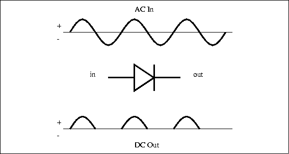
rectifier. The circuits gets its name from the fact that the output is just the positive half of the input waveform. A full-wave rectifier circuit (shown in Figure 4.16) uses four diodes arranged so that both polarities of the input waveform can be used at the output.
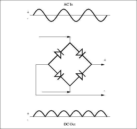
The full-wave circuit is more efficient than the half-wave one.
No comments:
Post a Comment